The image above is for illustration purpose only. The actual module may vary from the one presented here.
* Current consumption does not include the loads on the power outputs, alarm bus and AUX outputs.
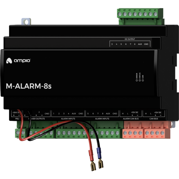
Module M-ALARM-8s is a component of the Ampio system. Required voltage to power the module is 18 — 24V DC. The module is controlled via CAN bus.
The M-ALARM-8s module has the functionality of a control panel, with eight alarm inputs, two power outputs and six binary OC outputs. The module is powered by a power supply independent of the rest of the building automation installation and provides emergency power via a plug-in battery. It also allows a segment of the alarm CAN bus to be isolated - the supply voltage of the connected devices is also maintained by the M-ALARM-8s module.
The module has bi-state inputs that go into an active state when they are shorted to ground, allowing for the connection of any devices with potential-free contact outputs or optocoupler outputs. Such devices may include, in particular, reed switches and other alarm devices.
Depending on the configuration, alarm inputs can work with devices with the following types of contacts:
In addition to alarm applications, the inputs can be used as general purpose inputs in the case of any devices with potential-free contact outputs, e.g. wall switches, reed switches, buttons, switches, etc. They can also be used for integration with devices with potential-free relay outputs or optocoupler outputs with a collector voltage greater than 12V.
The module has open-collector outputs to allow integration with devices that have inputs with a pull-up resistor. It is also possible to control resistive loads supplied with voltages up to 20V DC. Control of loads of a moderate inductive nature, in particular relays, is also permitted. Internally, each output allows the connected line to be shorted to the module ground.
The maximum current load of the module’s OC outputs M-ALARM-8s is 100mA.
Unlike the OC outputs found in the other modules in the Ampio range, the outputs of the M-ALARM-8s module do not allow smooth control - only full on/off of individual outputs is possible.
The module has power outputs to supply and control resistive loads supplied with 12V DC, especially alarm sirens and other signalling devices. Control of loads of a moderate inductive nature, particularly relays, is also permitted.
Internally, control of the devices is achieved by keying the ground connection. For proper functionality, the ground of the connected devices must not be connected to the ground of the module and the power supply other than via the - terminal of the power output.
Individual alarm zones can be armed and disarmed via M-DOT-M18 panels using PIN codes defined in the module. Communication between devices related to the implementation of the described functionality is encrypted and protected against replay attacks.
The module allows a segment of the alarm CAN bus to be isolated. Devices installed in this segment can communicate with devices located in the rest of the building automation bus.
The power supply to the alarm bus devices is maintained in the event of a mains power failure. In addition, damage to the rest of the building automation bus, such as an overload of the power line or short-circuit of the data lines, does not affect the operation of the alarm bus devices.
The current consumption of the devices operating within the alarm bus must not exceed 1A.
The module is powered by a power supply independent of the other building automation bus devices connected to the CAN BUS connector. The connection of a gel battery with a voltage of 12V provides the module’s power backup functionality.
The AUX outputs of the device provide 12V DC, which can be used to power devices associated with the operation of the alarm system. With this connection, the power supply to these devices will also be backed up in the event of a mains voltage failure.
The power supply to devices connected to the module’s power outputs and Ampio devices connected to the alarm bus is also sustained.
The maximum current load generated by all devices connected to the AUX outputs, power outputs and alarm bus should not exceed 3A. If a battery is connected to the device, it is permissible to temporarily exceed this value.
The module is designed for mounting on a 35mm DIN rail. The module’s width is 160mm, 9 spaces/modules in DB. In order to start the module, it must be connected to the CAN bus. The bus of the Ampio system consists of four wires - two for power and two for communication between the modules.
The module has two CAN bus connectors. The connector labelled ALARM CAN BUS is the building automation alarm bus interface with power supply back-up.
In addition to the CAN bus connectors, the unit has six connectors with screw terminals. These allow connections of the unit’s power supply, power and OC outputs and alarm inputs. The terminals labelled AUX provide a sustained 12V DC voltage for supplying external devices associated with the operation of the alarm system, such as sensors, alarm sirens or other signalling devices.
The module is powered entirely by the connected power supply 18 — 24V DC - it does not draw power from the connected CAN bus. It, therefore, does not need to be included in the power balance of the basic building automation bus.
Two 25 cm long cables terminated with female flat connectors are led from the housing of the device, to which a 12V gel battery with 6.3mm wide terminals should be connected. It is permissible to use extension cables terminated with suitable flat connectors.
On the front of the module there are signalling LED indicators. The green LED with the label CAN indicates the status of communication on the CAN bus:
In addition to the LED indicating the status of the communication bus, there are two more red LEDs on the front of the device:
The module is programmed with the use of the Ampio Designer software. It allows you to modify the parameters of the module and define its behaviour in response to signals directly available to the module as well as general information coming from all devices present in the home automation bus.
The MAC addresses of modules configured to work with the M-ALARM-8s module cannot be changed at any stage of configuration.
Dimensions expressed in millimeters.
 Click to enlarge and open in a new tab.
